

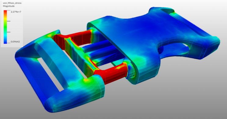
While many parts may work well initially, they often fail in service due to fatigue failure caused by repeated cyclic loading. Characterizing the capability of a material to survive the many cycles a component may experience during its lifetime is the aim of fatigue analysis. In a general sense, Fatigue Analysis has three main methods, Strain Life, Stress Life, and Fracture Mechanics; the first two being available within the ANSYS Fatigue Module.
Total Life Approaches
- High cycle fatigue (Stress life)
- Low cycle fatigue (Strain life)
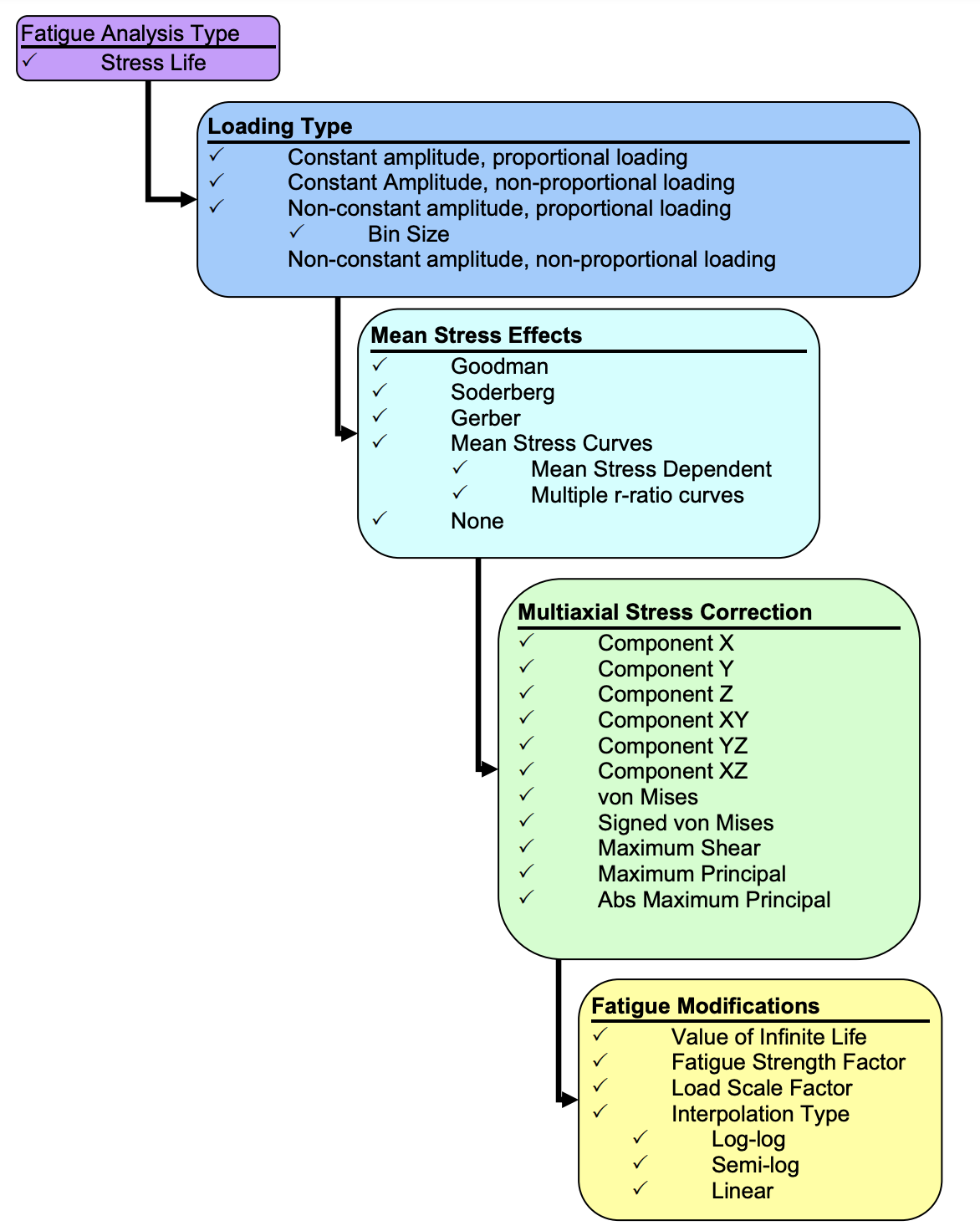
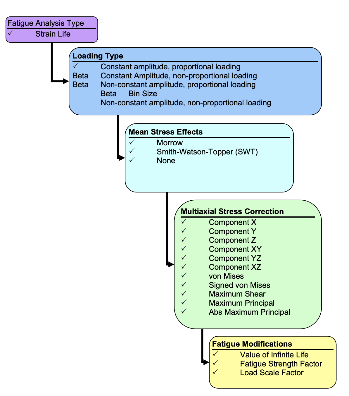
The capability of the Ansys Workbench Fatigue Module is shown in the flowchart below.
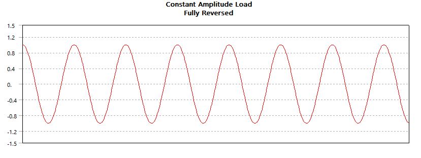
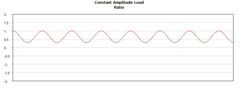
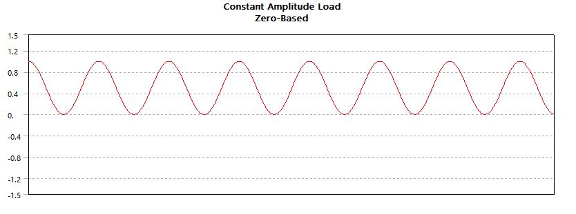
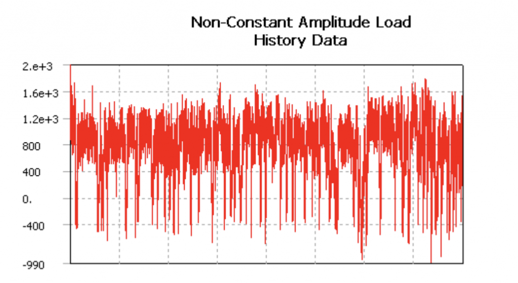
Types of Cyclic Loading
- Fully Reversed
- Zero Based
- Ratio
- History Data
Mean Stress Correction
Once you have made the decision on which type of fatigue analysis to perform, Stress Life or Strain Life, and have determined your loading type, the next decision is whether to apply a mean stress correction. Cyclic fatigue properties of a material are often obtained from completely reversed, constant amplitude tests. Actual components seldom experience this pure type of loading, since some mean stress is usually present. If the loading is other than fully reversed, a mean stress exists and may be accounted for.
Types of Results
Just like some of the input decisions change depending upon whether you are performing a Stress Life or a Strain Life analysis, calculations and results can be dependent upon the type of fatigue analysis. Results can range from contour plots of a specific result over the whole model to information about the most damaged point in the model (or the most damaged point in the scope of the result). Results that are common to both types of fatigue analyses are listed below:
- Fatigue life
- Fatigue damage at a specified design life
- Fatigue factor of safety at a specified design life
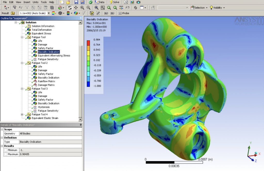
- Stress biaxiality
- Fatigue sensitivity chart
- Rainflow matrix output (Beta for Strain Life at 10.0)
- Damage matrix output (Beta for Strain Life at 10.0)
General Fatigue Results
1-Fatigue Life
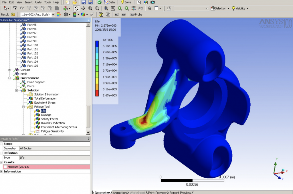
Fatigue Life can be over the whole model or scoped just like any other contour result in Workbench (i.e. parts, surfaces, edges, and vertices). In addition, this and any contour result may be exported to a tab-delimited text file by a right mouse button click on the result. This result contour plot shows the available life for the given fatigue analysis. If loading is of constant amplitude, this represents the number of cycles until the part will fail due to fatigue. If loading is non-constant, this represents the number of loading blocks until failure.
2- Fatigue Damage
Fatigue Damage is a contour plot of the fatigue damage at a given design life. Fatigue damage is defined as the design life divided by the available life. This result may be scoped. The default design life may be set through the Control Panel. For Fatigue Damage, values greater than 1 indicate failure before the design life is reached.
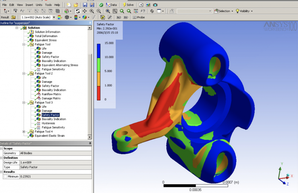
3- Fatigue Safety Factor
Fatigue Safety Factor is a contour plot of the factor of safety with respect to a fatigue failure at a given design life. The maximum Factor of Safety displayed is 15. Like damage and life, this result may be scoped. For Fatigue Safety Factor, values less than one indicate failure before the design life is reached.
References
support.ansys.com


Louie
How can I find ‘Fatigue Strength Factor(Kf)’ in Ansys. Although I search every article, I can not find any method for calculating. Can you help me, please?
özgün
Dear Louie,
As far as I know, Kf is associated with such factors, as surface roughness, notch effects, etc. Therefore, I do not think it is a straightforward process to retrieve from a simple solution. You may think about getting it through user-defined results. However, surface roughness can still be challenging for FE solutions.
Louie
Thank you so much for help. I found some equations about this topic.
Kf = 1+ q(kt -1)
q=1/(1 + a/r)
a= ((300/Su)^1.8)/1000
These are simple equations, however I want to know something. As you said, notch effect is associated with Kf. If there are many holes, radius in a model, how can I calculate the Notch sensitivity factor?
Should I do notch test for model?