

Choosing the appropriate contact type depending on the type of problem you are trying to solve is often tricky. Particularly, a number of new Ansys users are very confused about the differences among the contact types; such as Frictionless, Rough, Frictional, No separation. In this article, we will explain the general features of contact behaviours with illustrations.
1. Bonded
This is the default configuration and applies to all contact regions (surfaces, solids, lines, faces, edges). If contact regions are bonded, then no sliding or separation between faces or edges is allowed. Think of the region as glued. This type of contact allows for a linear solution since the contact length/area will not change during the application of the load. If contact is determined on the mathematical model, any gaps will be closed and any initial penetration will be ignored. [Not supported for Rigid Dynamics. Fixed joint can be used instead.]
2. No Separation
No separation contact: Once the contact is detected, then the target and contact surface are tied up for the rest of the analysis. The slide is possible, but the nodes in contact are bonded to the target surface in the normal direction.
3. Frictionless
This setting models standard unilateral contact; that is, normal pressure equals zero if separation occurs. Thus gaps can form in the model between bodies depending on the loading. This solution is nonlinear because the area of contact may change as the load is applied. A zero coefficient of friction is assumed, thus allowing free sliding. The model should be well constrained when using this contact setting. Weak springs are added to the assembly to help stabilize the model in order to achieve a reasonable solution.
4. Frictional

In this setting, the two contacting geometries can carry shear stresses up to a certain magnitude across their interface before they start sliding relative to each other. This state is known as “sticking.” The model defines an equivalent shear stress at which sliding on the geometry begins as a fraction of the contact pressure. Once the shear stress is exceeded, the two geometries will slide relative to each other. The coefficient of friction can be any nonnegative value. [Not supported for Rigid Dynamics. Forced Frictional Sliding should be used instead.]
5. Rough

Similar to the frictionless setting, these setting models perfectly rough frictional contact where there is no sliding. It only applies to regions of faces (for 3D solids) or edges (for 2D plates). By default, no automatic closing of gaps is performed. This case corresponds to an infinite friction coefficient between the contacting bodies. [Not supported for Explicit Dynamics analyses.]


khatere dakhili
hi
thanks for your useful post
I’m looking for the difference between the formulation, whether MPC or Pure Penalty..
Do you have any resources?
özgün
Hi Khatere,
Thank you for your interest.
This might be the answer to your question;
https://www.sharcnet.ca/Software/Ansys/16.2.3/en-us/help/wb_sim/ds_contact_theory.html
enzo
can someone please help me with some refereces about contact types ???
özgün
I would recommend you to have a look at ansys user guide
Soheil
Hi
Thanks for your post.
I want to model contact between helical gear. But i don’t know which kind of contact and solver should use.
Do you have any resources?
Ben Ofwono
Hi, what type of contact would be best for confined masonry walls interacting with RC columns?
PRANSHU PRATYUSHA
Hi,
Thank you for such a simple explanation. Can you please give a real life example where rough contact can be/is used?
özgün
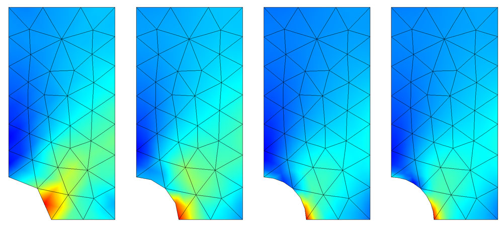
I have added illustrations for the contact types
Harun
Hi,
Thank you for sharing. Could you give more examples for complex surface contact? or share any resource? For example, for a flat surface and convex surface. I mean, you will understand what I mean when you look at the Spinal (PLIF, TLIF…)cages shape and ASTM F2077 test standard.
oguz
Eline sağlık kardeşim çok güzel içerik hazırlamışsın
Sankalp
How can I rotate a disk in Ansys workbench mechanical
IHB
Add revolute join and angular velocity
A.Esmaeili
Hi
How can I simulate a structure with some bolt and nuts?