Building an effective and efficient finite element model can be a difficult practice for engineering. Particularly, if you are a new learner finite element user, this sometimes gets very frustrating. We expect the model to be able to answer questions as fast as possible with most accurate results. In this article we will be talking about 3 major life-saving tips to develop more effective finite element analysis.
1. Model Simplification
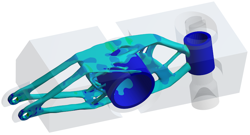
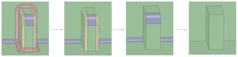
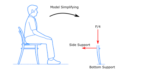
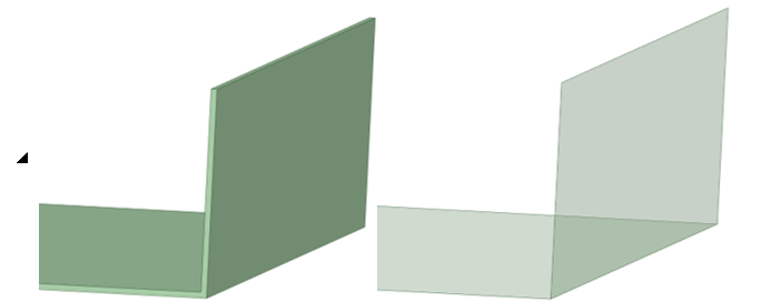
Simplifying your model comes first when starting your finite element analysis. Of course, model simplification is not possible in all situations, however, we can try our best to perform the FE analysis without using the unnecessary parts of the design. The model simplification sometimes can be either minor geometrical corrections (Figure 1); such as, removing small fillets/rounds which will not affect the global displacement calculations, or major component reductions (Figure 2), for giving a very basic example, you do not need to model the whole chair and person to analyse if the chair legs will withstand the maximum load of 1000 N. You can simply degrade the forces affecting the legs using remote connections (You read more about remote points here).
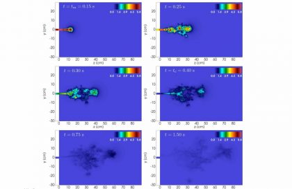
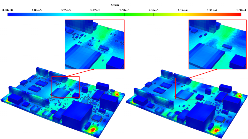
More of an advanced simplifying; Mechanical shock results show negligible global and local results when very small chip components are included (left) vs. when they are excluded (right) in Figure 3.
You can also take the simplifying to further stage although in very complicated cases using submodeling. (Read more about submodeling)
2. Appropriate Mesh Selection
We have known that there are a number of properties we can control during mesh operation such as; defeaturing, mesh size, advance sizing, refinement, proximity etc. (Here you can learn more about meshing properties) However, here we would like to talk about more choosing the correct and most efficient element types for your solutions. More often than not, CAD geometry will be composed entirely of three-dimensional bodies. However, in an FEA model, it may be advantageous to mesh some of those bodies with shell elements rather than solid 3D elements.
Shell elements are 2D approximations of the 3D geometry that store the thickness of a body as a physical property. They can be used for thin-walled geometries with a length much greater than the thickness of the body, and when the shear deformation is insignificant (e.g., a sheet metal chassis or the walls on a soda can). There are also special shell and beam reinforcement elements that can be used to model the thin copper layers inside a printed circuit board (PCB). New features in Ansys Sherlock allow for the rapid generation of these reinforcement geometries. These reinforcements enable the user to capture the effect the traces have on the board deformations efficiently.
It may seem intuitive to assume that 3D meshing yields more detail, which provides more accurate results. But this is not always the case. Particularly in cases of large bending, solid elements often create artificially stiff structures when they are used to mesh thin-walled geometries, resulting in inaccurate simulations. In addition, it can be very difficult to refine the mesh and generate enough elements through the thickness of a thin-walled structure to achieve accurate displacement and stress results.
Furthermore, if the geometry is complex enough, thin-walled structures may result in a poor-quality mesh when solid elements are used, creating sliver-like elements with poor aspect ratios, negatively affecting results.
2.1 Hex or Tet Elements
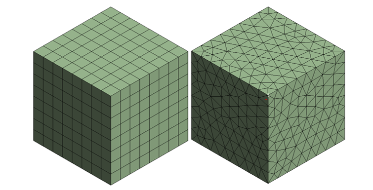
When determining whether to use hexahedral (hex-six face) elements or tetrahedral (tet- three face) elements in an FEA model configuration, it’s important to keep in mind the overall shape and complexity of the object itself. The general rule of thumb is to mesh with hexahedral elements if possible. Hex or “brick” elements generally result in more accurate results at lower element counts than tetrahedral elements. However, if the object contains acute angles or other complex geometries, it may be necessary to mesh with tetrahedral elements.
It is preferable to simplify the model enough to mesh it entirely with bricks, but this is not always feasible. For complex geometries that require tet meshes, take care to ensure the mesh does not result in inaccurate results. This usually means higher element counts, high order elements and longer run times.
For these reasons, any model simplifications like fillet removal or body splitting that allow for hex meshing without significantly changing the geometry are highly recommended.
2.2 Mesh Size and Order
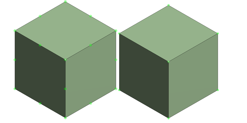
Mesh size simply refers to the characteristic edge length of an element. A smaller mesh size will result in more elements in the model, resulting in longer run times and more accurate results. First-order elements have nodes only at the corners of the elements (linear elements) and calculate displacement linearly between nodes. Second-order elements (quadratic elements ) include midside nodes between the corners and calculate displacement quadratically. The additional detail in second-order elements typically results in increased accuracy, but at a significantly increased computational cost.
At this point we should ask ourselves that do we really need these centre nodes in our analysis? How precisely will they affect our solution? It is better to find a balance between order and size of the elements.
3. Finding Correct Load Application
Determining proper load applications is an important analysis step. Load applications are the model inputs that the object is being tested for, such as a specific event like a thermal cycle, shock from a drop, vibration or static flexure.
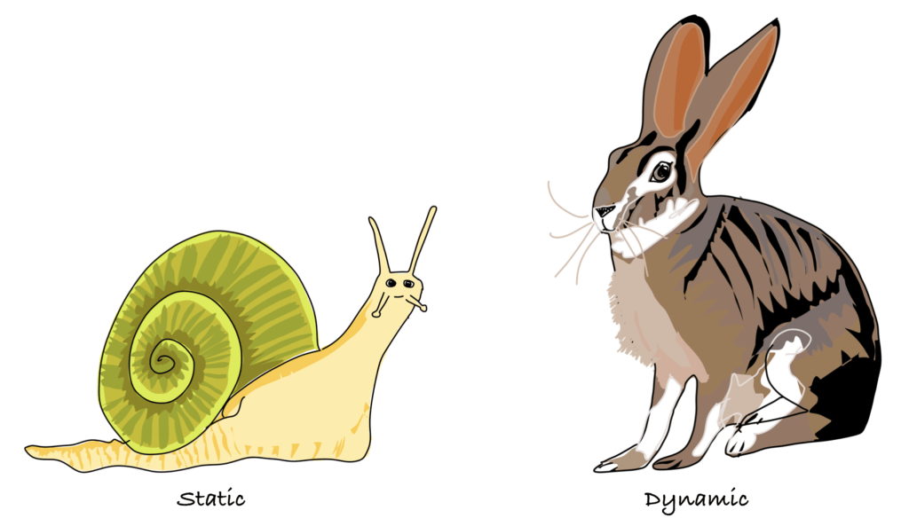
One common example is determining whether loads applied should be applied as static or transient. For example, if an engineer is simulating the flexure of a structure during assembly, it may be acceptable to model the load as a static displacement because strain rates are likely to be much slower and results time-independent. However, if an engineer is modeling a similar deflection caused by dropping the same assembly, they would likely need to use a transient model to capture the associated inertial effects, because the application time of the load is much faster and time-dependent effects must be captured.
The same real-world event is not always equal in the FEA world depending on the desired outcome of the analysis. It’s important to always keep in mind the real-world stressors the object will likely face and how those stressors could affect the component of interest. Inputting these nuances properly will result in an analysis that is accurate, valid and actionable.
Conclusion
Finite element analysis is an endless world and you will keep facing unique problems day by day. We believe that these suggestions will differ depending upon the type of your analysis and what you want to achieve. However, we still believe that these basic and fundamental improvements will have a significant effect on your solution time.
References
1- ansys.com/blog
2-For rabbit and snail, feaforall.com