Contact types and conditions are among the most challenging points for Ansys Workbench users. However, due to the fact that contact properties are rather complicated, therefore, we will divide this topic into Advanced Contacts in Ansys Workbench 1 and 2.
Mainly, rigid body motion can occur prior to static analysis in case contact conditions are not adequately established.
The figure below shows a contact-target example with an initial gap.
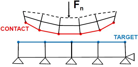
In this example, it is possible to fail the static solver because an unintended initial gap is present and force-based loading is applied.
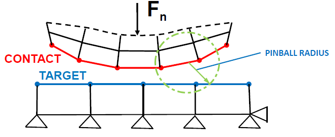
Pinball Radius
For linear contacts ( Bonded or No Separation ), a large enough Pinball Radius may
allow an initial gap between the Contact and Target surfaces to be ignored.
For nonlinear contact ( Frictional , Rough , or Frictionless ), an initial gap is not
automatically ignored.
Contact Surface Offset
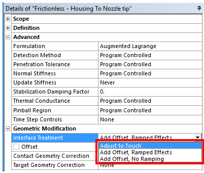
In order to sort and solve the unintended gap problem between contact and target, there are options under the Interface Treatment which internally offset the contact surfaces and thus close the gap.
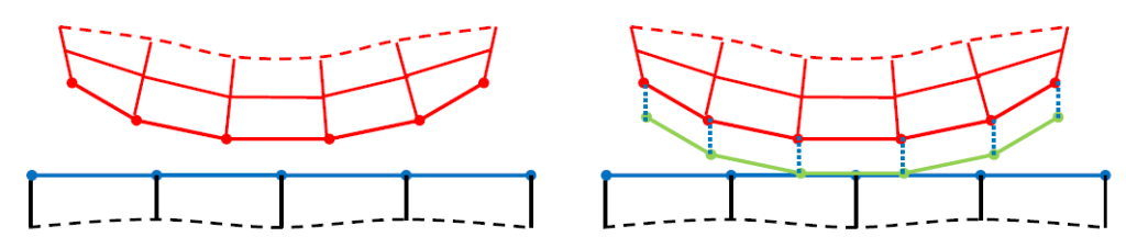
The illustration on left shows the original mesh. The red mesh is associated with the Contact
surfaces and the blue mesh is associated with the Target surfaces.
The Contact surfaces can be mathematically offset by a certain amount, as shown in light
green in the illustration at right. This adjustment will effectively close the gap and cause the
initial status of the contact region to be Closed.
This feature is a mathematical adjustment only, internal to the contact elements. The mesh
(nodes and elements) and the geometry are not altered. The position of the contact surface is
simply “interpreted” by the contact detection algorithms as having been offset by a specified
amount.
This feature, however, imparts an effective change in geometry at the contact interface, since
a small “rigid” region is created between the actual mesh and the offset contact surfaces.
This feature is intended for applications where the applied adjustment is small enough to
have a negligible effect on the results of interest.
This feature has proven to be a useful tool to establish initial contact in static analyses
without having to go through the (sometimes significant) additional effort required to modify
the CAD geometry.
In the Contact Region Details view, the user may select Adjust to Touch or Add Offset
Adjust to Touch causes Mechanical to determine and apply the contact offset necessary to close the gap and put the contact region into a “just touching” condition. Note that the contact status must be near the field open (that is, the Pinball Region must envelop the gap) for this to work. If all contact elements are far-field open, no adjustment will be made.
Add Offset allows the user to specify any desired positive or negative distance to offset the contact surfaces. A positive value will tend to close a gap while a negative value will tend to open a gap.
This approach can be used to model initial interference fits without modifying the geometry: model the geometry in a just touching condition and use a positive Add Offset value to implement the interference.
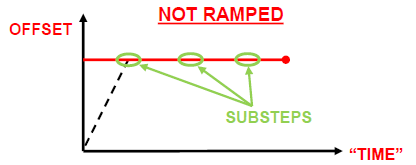
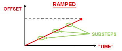
Add Offset, Ramped effect
Add Offset, Ramped Effects to ramp the interference linearly over all substeps in the load step. This is a useful technique to enhance convergence for challenging interference problems.
Add Offset, No Ramping
This method applies the interference all at once in the first substep of the load step.