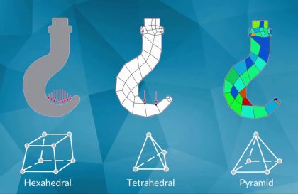
Supports are used to represent parts that are not present in the model but are interacting with it. Supports help truncate the domain, which helps in efficiently obtaining numerically accurate results without modelling parts of the geometry that are not of primary interest. There are different types of support available, and choosing the appropriate support is essential as it assures that the simulation model will properly represent the boundary condition.
Support types in Ansys Mechanical
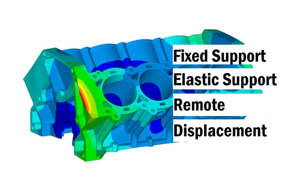
- Fixed support
- Displacement support
- Frictionless support
- Cylindrical support
- Compression only support
- Elastic support
- Remote Displacement support
Fixed Support
In this support condition, all the degrees of freedom are fixed. The selected support/surface/edge or point is restricted from displacement and rotation. Beams fixed to the walls are shown as one of the great examples of this type of support.

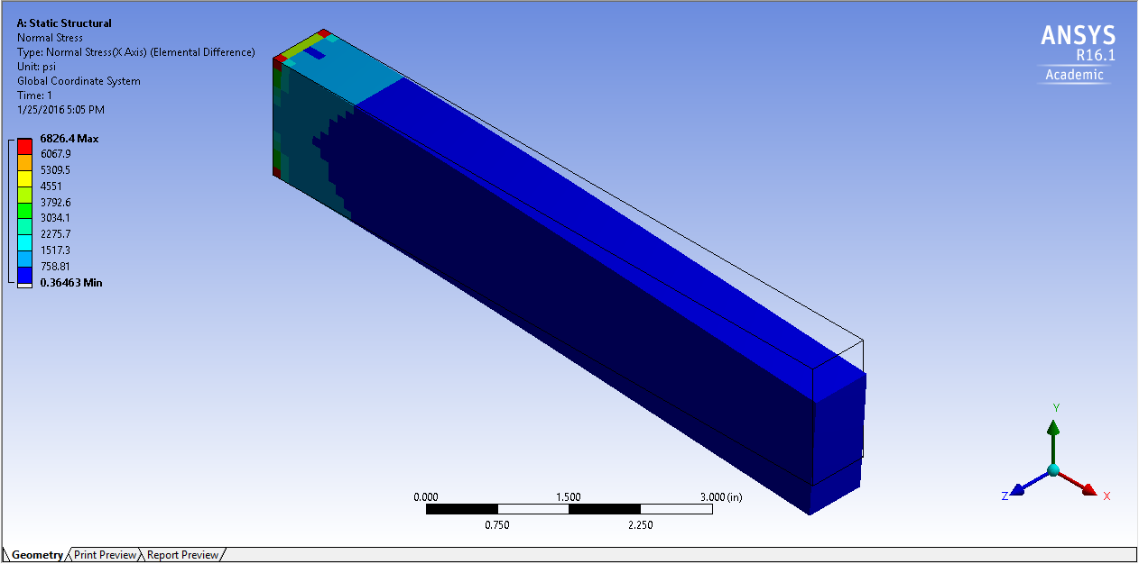
However, make sure that your model is not over-constrained. One of the biggest issues that users often experience is having peak stress points due to being overconstrained. Because your fixed supported surface cannot have any degree of freedom, it is likely to observe local peak stress areas.
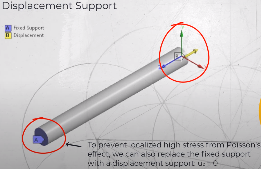
Displacement Support
Displacement support specifies a zero or non-zero displacement to any of three orthogonal directions. In other words, you can restrain or give movement to your selected surface/edge/point in any direction (x,y,z). For instance while performing a standard tensile test, test specimens are pulled in a uniaxial direction. This phenomenon can be represented with displacement support.
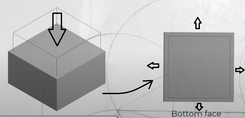
Frictionless Support
This type of support constrains translational movement in the direction normal to the surface. However, it does not restrict in-plane motion. For instance, let’s think about a cube subjected to pressure in the vertical direction. The cube’s bottom face is subjected to frictionless support, therefore while it restricts the cube’s bottom from moving in the vertical direction, it allows the bottom face to enlarge in-plane direction. It is also applicable in vice versa.
Cylindrical Support
The cylindrical support allows to define a radial clearance over some widths and an axial clearance between two parts. It can be used to model a ring on or in a shaft. The constraint can be rigid or stiffness can be defined.
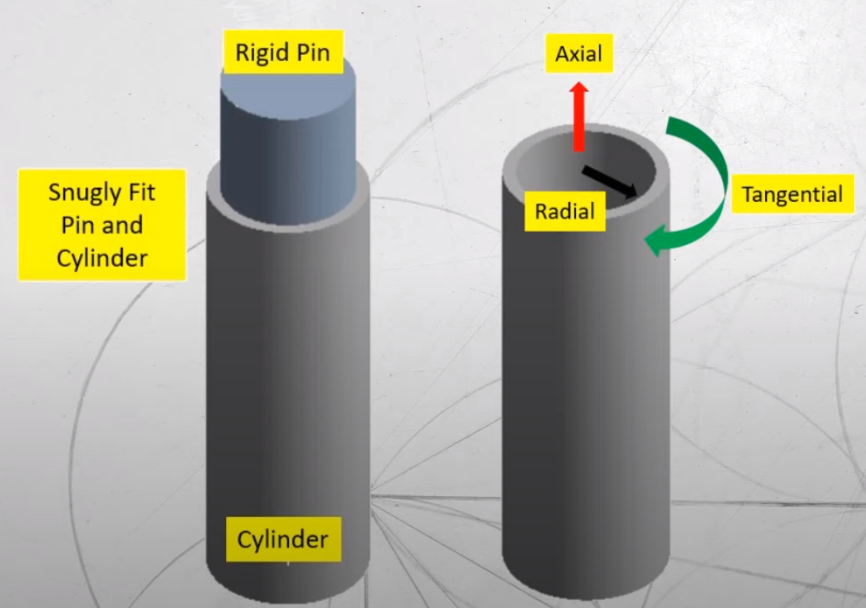
You can also apply cylindrical support to holes. If the shaft is only free to rotate, the tangential force will be free and axial and radial supports will be fixed. However, please be careful cylindrical supports are often valid in small deflections, therefore refrain from using them in large deflection analysis.
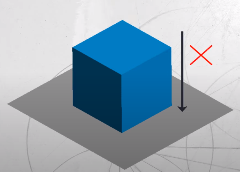
Compression Only Support
Compression only support allows the surface move in tangential direction, lift off in negative normal direction but cannot move in the positive normal direction.
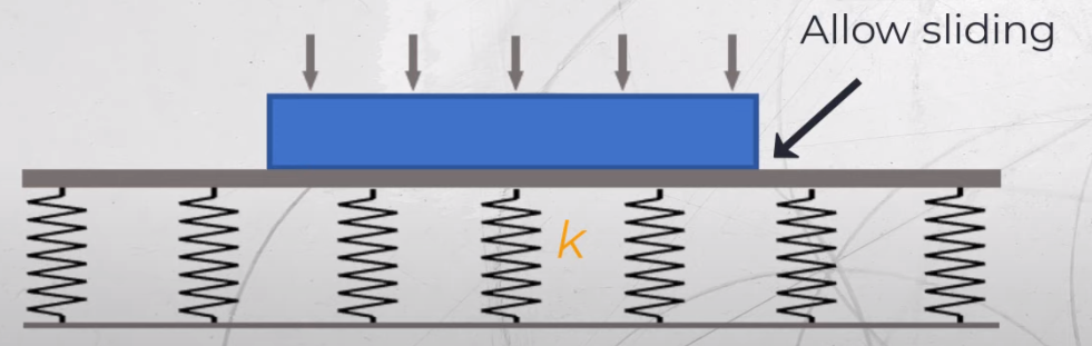
Elastic Support
An Elastic Support defines an elastic foundation between the selected faces of a part or assembly and the ground. The Elastic Support is based on a Foundation Stiffness, which is defined as the pressure required to produce a unit normal deflection of the foundation. Elastic Support applies flexible frictionless support to a face.
Elastic support is used to represent foundation stiffness. For example; Elastic support can be used to model piles which are used to support LNG tanks, Another example is base frame or skid are mounted on foundations, which can be model using elastic supports in FEA.
Remote Displacement Support
Remote displacement can be considered one of the most important and practical support types in ansys workbench. In basic terms, it is the easiest way of showing simply supported beams which boundary conditions are that one end is only able to pivot, and the other can both rotate and move in a lateral direction. More general in this boundary condition, you can control both rotations and displacement in the selected axis. This BC contains 6 numbers of degrees of freedom, rotations and displacements in x,y and z.

References
1-Ansys Learning
2-graspengineering.com