The finite element method (FEM) has been used as a powerful tool to solve engineering problems since the late 50s. The calculations were, at that time, carried out by hand and the method was force-based, not displacement-based as we use it today. Thanks to advances in the computer industry, a variety of FE commercial software have been developed. Ansys can be considered one of the most used FEM software globally with a wide range of products, such as; Fluent, Workbench etc.
Beginner Workbench users occasionally are facing the problem of choosing the correct meshing method, Tetrahedrons, Hexdominant, Sweep, Multizone or Cartesian, to obtain a good mesh quality. However, before explaining what those methods stand for, We’d better start with what does the element type mean?
Element Types
Probably senior Ansys Classic (APDL) users know very well that choosing an appropriate element type is vital for finite element solutions. In the past, it was mandatory to define the correct element type which was often a 2-dimensional element such as triangular or quadratic. In short, choosing the correct element defines your FE model properties, such as being a solid block, behaving as a load-carrying beam or a plain surface.
One of the main reasons for using special types of elements for different finite element problems is the advantage of reducing solving time. Because sometimes If you have a simple loading and would like to investigate only a stress on the surface, you may not need to use a very detailed mesh or element type. Therefore, it is always better to simplify the model as much as you can. We will not go into the details of beams, plates or solid elements but it is always good to know what exactly happens in the background of Ansys Workbench.
In a 2D form, we can classify the elements as triangular and quadratic depending on their shape.
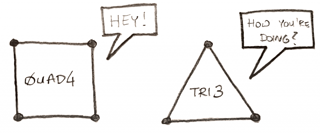
These elements can also vary depending on the number of nodes they have, such as TRI3: 3nodes triangle, TRI6: 6 nodes triangle, QUAD4: 4nodes quadratic or QUAD8: 8 nodes quadratic. Basically, the higher number of nodes they have, the more accuracy in strain representation you expect.
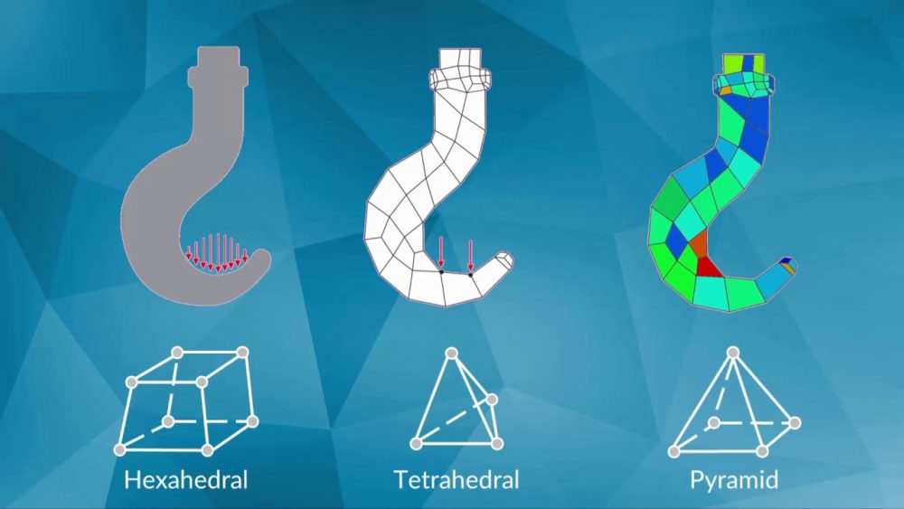
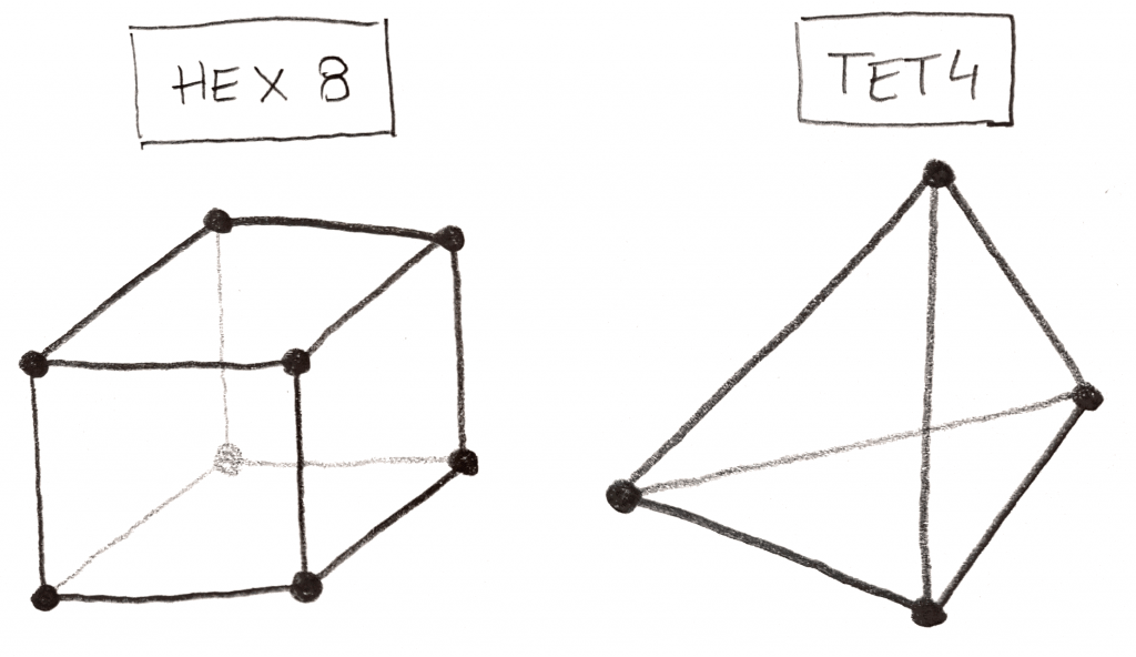
As for 3D elements, in basic terms, they are 3D versions of 2D elements and we call them tetrahedral and hexahedrons. They also can vary based on the number of nodes, TET4, TET10, HEX8, HEX20 etc.
Mesh Methods in Workbench
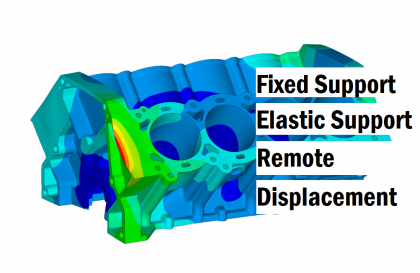
In Workbench software, you can let the software decide what mesh method will be used automatically based on your boundary conditions or you choose some methods to build your mesh structure. However, I would like to emphasize a point that in the user interface (If you do not use APDL commands) the software does not let you choose a specific element, SOLID186, SHELL 181 etc. It rather lets you control the shape of the elements using the meshing methods of Tetrahedrons, Hex Dominant, Sweep, Multizone and Cartesian.
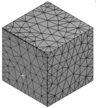
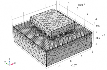
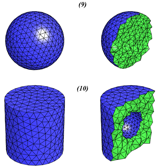
Tetrahedrons
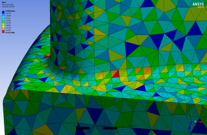
In this method, triangular elements are used for creating your mesh. Sometimes might see prismatic elements also in your mesh geometry as well as the triangular elements. This method is preferred for relatively complex geometries such as grooves, channels, and corners with angles. Tetrahedrons can generate a higher number of cells than quadratic elements with the equivalent mesh size.
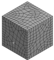
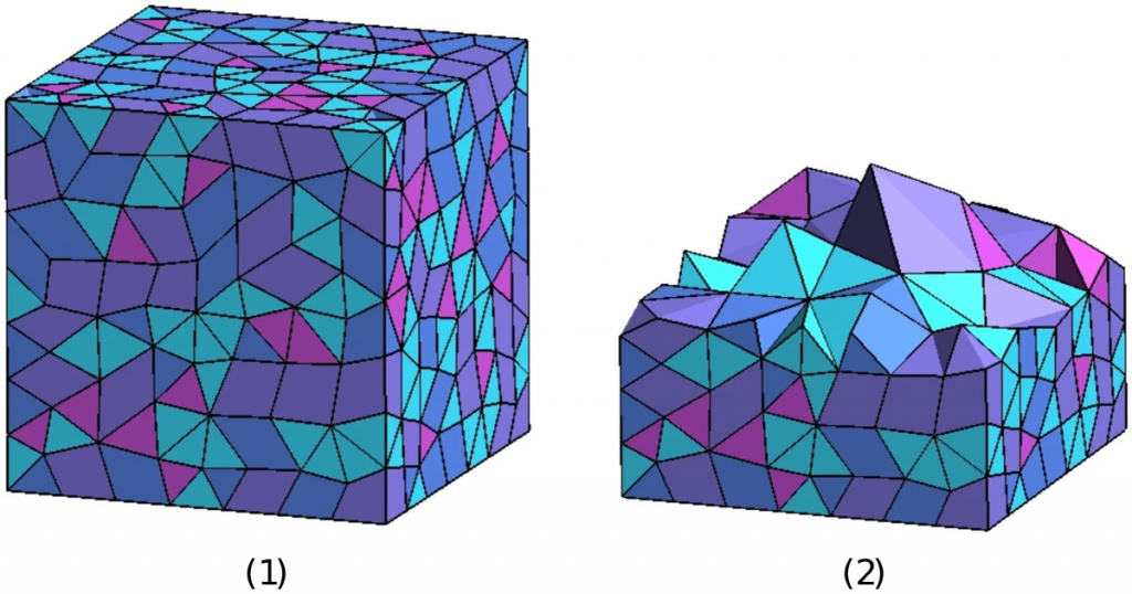
Hex Dominant
The goal of hex-dominant meshing is to generate meshes where hexahedral elements dominate, both in number and volume. However, this method relies on the triangle-merge technique which is used to recombine the triangles of the initial mesh into quadrilaterals. Therefore, using this method does not mean that all of your elements will be hexahedrons. You will still certainly observe many triangular or prismatic elements in the mesh geometry.
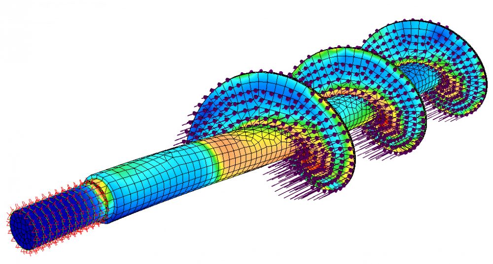
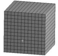
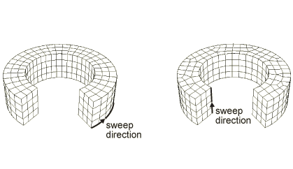
Sweep
A swept mesh refers to the method in which a face of volume is meshed (perhaps with high quality quadrilateral elements) and then “swept” through the body creating a volume mesh. The body must have a topologically constant cross-section to sweep through. (A circular face sweeps through a cylinder along the axis of the cylinder)
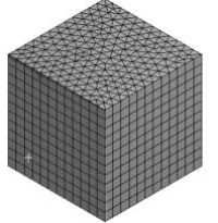
Multizone
Multizone is used when you are meshing single body parts that are too complicated for the traditional sweep approach. The MultiZone mesh method provides an automatic decomposition of geometry into mapped (structured/sweepable) regions and free (unstructured) regions. It automatically generates a pure hexahedral mesh where possible and then fills the more difficult to capture regions with unstructured mesh.
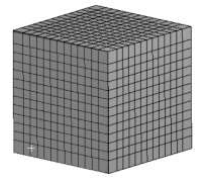
Cartesian
This Cartesian cut cell approach generates a mesh without the need for optimisation, thus removing a significant bottleneck in the simulation pipeline/
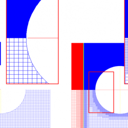
Since the cut cells created at the boundary can be arbitrarily small, they impose a severe constraint on the explicit stable time step for the simulation. The challenge is to overcome this ‘small cell problem’ by designing techniques to evolve the cut cells using the regular cell time-step without sacrificing stability and conservation.
References
1-enterfea.com
2-A frontal approach to hex-dominant mesh generation–Tristan Carrier Baudouin, Jean-François Remacle, Emilie Marchandise, François Henrotte & Christophe Geuzaine
3-Matthew Edmond from Quora – https://www.quora.com/What-is-sweep-meshing
4-https://www.lsc.phy.cam.ac.uk/research/cartesiancutcells
5-https://www.researchgate.net/publication/229047159_A_simple_mesh_generator_in_MATLAB/figures?lo=1
6-https://abaqus-docs.mit.edu/2017/English/SIMACAECAERefMap/simacae-c-mgnconcmeshingswept.htm